
Jumat, 16 Januari 2015
Rabu, 01 Januari 2014
Penyebab CCD/AP PCB rusak
Penyebab CCD/AP PCB rusak
canon ir6020/ir6000/ir5000 error E302 - 001
Penyebab Utama CCD / AP PCB rusak. Kabel rusak (hubung singkat, rangkaian terbuka).
Pembaca kontroler PCB rusak.
Mode Deteksi :
0001 Selama shading, pembaca kontroler PCB tidak berakhir shading dalam 1 detik.
0002 Dalam membaca stream, tepi putih akumulasi (pengolahan) tidak berakhir setelah jangka waktu 10 detik.
 Keterangan
diatas adalah translate google dari kode canon error E302. Berdasarkan
keterangan diatas menunjukan dengan jelas kerusakan seputar CCD kurang
lebih bagian optic/lensa tidak bekerja dengan baik, CCD unit Canon
ir6020 sangatlah mahal kalau kita search kemungkinan kisaran 2jt - 3jt
rupiah. Tapi anda jangan berkecil hati ...ada kemungkinan lain yaitu
kabel flexible penghubung AP PCB dengan CCD unit ada kemungkinan lepas
atau rusak. Seharusnya kerusakan E302 pada mesin fotocopy canon
kemungkinannya kecil sekali mengingat alat tersebut( kabel Flexible )
yang menghubungkan AP PCB dengan CCD unit tidak bergerak atau tidak
bergesekan dengan jalannya scanner atau hal lain. Berbagai kasus dan
pemikiran saya ambil kesimpulan kemungkinan usia mesin sudah sedikit
agak rewel kemungkinan besar sering nyangkut atau trouble lain yang
memaksa kita membuka pintu cover depan dan samping kemudian menutupnya
dengan keras! atau mesin tersebut sering sekali mendapat guncangan! ini
mungkin yang membuat kabel flexible tersebut terlepas atau kurang
kencang. Jadi bagi anda yang mengalami error E302 pada mesin mesin
fotocopy canon ir5000/ir6000/ir6020 coba cek kabel flexible penghubung
AP PCB dengan CCD unit apakah lepas atau kurang kencang atau kemungkinan
lain kabelnya rusak atau putus....jika putus atau rusak coba cari kabel
flexible tersebut di toko elektronik kemungkinan ada yang jual yang
pasti harganya pasti murah! semoga bermanfaat buat anda.....
Keterangan
diatas adalah translate google dari kode canon error E302. Berdasarkan
keterangan diatas menunjukan dengan jelas kerusakan seputar CCD kurang
lebih bagian optic/lensa tidak bekerja dengan baik, CCD unit Canon
ir6020 sangatlah mahal kalau kita search kemungkinan kisaran 2jt - 3jt
rupiah. Tapi anda jangan berkecil hati ...ada kemungkinan lain yaitu
kabel flexible penghubung AP PCB dengan CCD unit ada kemungkinan lepas
atau rusak. Seharusnya kerusakan E302 pada mesin fotocopy canon
kemungkinannya kecil sekali mengingat alat tersebut( kabel Flexible )
yang menghubungkan AP PCB dengan CCD unit tidak bergerak atau tidak
bergesekan dengan jalannya scanner atau hal lain. Berbagai kasus dan
pemikiran saya ambil kesimpulan kemungkinan usia mesin sudah sedikit
agak rewel kemungkinan besar sering nyangkut atau trouble lain yang
memaksa kita membuka pintu cover depan dan samping kemudian menutupnya
dengan keras! atau mesin tersebut sering sekali mendapat guncangan! ini
mungkin yang membuat kabel flexible tersebut terlepas atau kurang
kencang. Jadi bagi anda yang mengalami error E302 pada mesin mesin
fotocopy canon ir5000/ir6000/ir6020 coba cek kabel flexible penghubung
AP PCB dengan CCD unit apakah lepas atau kurang kencang atau kemungkinan
lain kabelnya rusak atau putus....jika putus atau rusak coba cari kabel
flexible tersebut di toko elektronik kemungkinan ada yang jual yang
pasti harganya pasti murah! semoga bermanfaat buat anda..... |
| Gambar 1 |
 |
| Gambar 2 |
Gambar 1. Penampakan CCD unit canon ir6020 yang sudah di buka penutupnya....
Gambar 2. kabel Flexible CCD yang rusak pengancingnya....maka di coba diperbaiki dengan isolasi terlihat warna biru
Gambar 3. penampakan dari jarak dekat....mudah2an bisa membantu...kalau cara ini masih tidak bisa terpaksa harus mengganti kabel flexible yang baru... Description: canon ir6020/ir6000/ir5000 error E302 - 001 Rating: 3.5 Reviewer: Deni Natanael ItemRevi
Senin, 02 Desember 2013
KODE ERROR
| Code | Cause | Remedy |
|---|---|---|
| E000 | The heater fails to heat.
After correcting the fault, be sure to reset the error. (COPIER>FUNCTION>CLEAR>ERR) |
|
| 0000 | After power-on, the reading of the main thermistor does not increase to 70 deg C or higher within 20 sec. | Replace the main/shutter thermistor.
Replace the DC controller PCB. |
| 0010 | The power has been turned off and then on without resetting the error. | Reset the error. (COPIER>FUNCTION>CLEAR>ERR) |
| E001 | There is an abnormal rise in temperature.
After correcting the fault, be sure to reset the error. (COPIER>FUNCTION>CLEAR>ERR) |
|
| 0001 | There is an error or an open circuit in the main thermistor, shutter thermistor, or sub thermistor. | Check the connector of each thermistor for any fault in connection and wiring.
Replace the thermistor in question. Replace the DC controller PCB. |
| 0002 | The reading of the main thermistor, shutter thermistor, or sub thermistor is 230 deg C or higher for 2 sec. | Replace the thermistor in question.
Replace the DC controller PCB. |
| 0003 | The reading is not 150 deg C or higher or 210 deg C or lower within 30 sec. | Cheak the connecting of the main/ sub/ shutter thermistors.
Check the mounting of the main/ sub/ shutter thermistors. Exchange the main/ sub/ shutter thermistors. Exchange the DC controller PCB. |
| 0010 | The power has been turned off and then back on without resetting the error. | Reset the error. (COPIER>FUNCTION>CLEAR>ERR) |
| E002 | There is an abnormal rise in temperature.
After correcting the fault, be sure to reset the error. (COPIER>FUNCTION>CLEAR>ERR) |
|
| 0000 | The reading of the main thermistor is not 100 deg C 12 sec after it has exceeded 70 deg C. | Check the connector of the main/shutter thermistor for any fault in connection
and wiring.
Check the main/shutter thermistor for mounting condition. Replace the main/shutter thermistor. Replace the fixing heater unit. Replace the DC controller PCB. |
| 0001 | The reading of the main thermistor is not 150 deg C 15 sec after it has - Replace the DC controller PCB. exceeded 100 deg C. | |
| 0010 | The power has been turned off and then back on without resetting the error. | Reset the error. (COPIER>FUNCTION>CLEAR>ERR) |
| E003 | There is an abnormal rise in temperature.
After correcting the fault, be sure to reset the error. (COPIER>FUNCTION>CLEAR>ERR) |
|
| 0000 | The reading of the main thermistor is lower than 70 deg C for 2 sec or more after it has exceeded 100 deg C. | Check the connector of the main/shutter thermistor for any fault in connection
and wiring.
Check the main/shutter thermistor for mounting condition. Replace the main/shutter thermistor. Replace the fixing heater unit. Replace the DC controller PCB. |
| 0010 | The power has been turned off and then back on without resetting the error. | Reset the error. (COPIER>FUNCTION>CLEAR>ERR) |
| E004 | The IH power supply is faulty/the IH control mechanism is faulty.
After correcting the fault, be sure to reset the error. (COPIER>FUNCTION>CLEAR>ERR) |
|
| 0010 | The power has been turned off and then back on without resetting the error. | Reset the error. (COPIER>FUNCTION>CLEAR>ERR) |
| 0101 | There is a mismatch between the input voltage and the IH power supply ID. | Replace the fixing heater power supply with one designed for the country of installation (voltage). |
| 0102 | The IH current is faulty. (current leakage) | Check the connector for any fault in connection.
Replace the fixing heater power supply. Replace the DC controller PCB. |
| 0103 | The IH current is faulty. (no current) | |
| 0104 | There is an IH over-current. | |
| 0105 | The IH input voltage is too high. | |
| 0106 | The IH input voltage is too low. | |
| 0201 | At power-on (or, when IH is at reset), the IH control mechanism is not in an initial state. | |
| 0202 | At IH start-up, the IH control enable flag is not set within 1 sec after the start flag is set. | |
| 0203 | With IH at rest, the IH control flag is not released. | |
| 0204 | The 12-V power supply (IH relay) is identified as being off. | |
| 0205 | At IH start-up, the PWM/ON data is faulty ('0' or 'FFFF') | Replace the DC controller PCB. |
| E005 | There is no fixing web/there is an error in the detection of web solenoid connection. | |
| 0000 | The absence of the fixing web has been detected for 5 sec or more. | Replace the fixing web.
Replace the fixing web length sensor. Replace the DC controller PCB. After correcting the fault, be sure to reset the fixing web counter reading. (COPIER>COUNTER>MISC>FIX-WEB) |
| 0001 | At power-on, the connection of the web solenoid is not detected. | Check the connector for any fault in connection.
Replace the solenoid. |
| 0010 | The power has been turned off and then back on without resetting the error. | Reset the fixing web counter. (COPIER>COUNTER>MISC>FIX-WEB) |
| E010 | There is a feed motor error. | |
| 0000 | The FG signal of the feed motor does not arrive for 2 sec or more even when the feed motor has been turned on. | Check the connector for any fault in connection.
Replace the motor. |
| E012 | There is a drum motor error. | |
| 0000 | The FG signal of the drum motor does snot arrive for 2 sec or more even when the drum motor has been turned on. | Check the connector for any fault in connection.
Replace the motor. |
| E013 | The waste toner pipe is clogged. | |
| 0000 | The waste toner pipe is identified as being clogged for 4 sec or more. | Check the connector for any fault in connection.
Replace the waste toner feedscrew lock detecting switch. Replace the waste toner feed unit. Replace the DC controller PCB. |
| 0010 | The power has been turned off and then back on without resetting the error. | |
| E014 | There is a fixing motor error. | |
| 0000 | The Phase lock signal of the fixing motor does not arrive for 2 sec even when the fixing motor has been turned on. | Check the connector for any fault in connection.
Replace the motor. |
| E020 | There is no toner in the developing assembly; there is an error in the detection of developing toner sensor connection; there is an error in the detection of hopper toner sensor connection | |
| 0000 | The presence of toner is detected inside the sub hopper and, in addition, the absence of toner is detected inside developing assembly for 120 sec continuously even when operation has been under way for the supply of toner to the developing assembly. | Check the connector of the developing toner sensor for any fault in connection.
Replace the developing toner sensor. Replace the hopper toner sensor. |
| 0001 | At power-on, the connection of the developing assembly toner sensor is not detected. | Check the connector for any fault in connection.
Replace the sensor. |
| 0002 | At power-on, the connection of the developing hopper toner sensor is not detected. | |
| E025 | There is a toner feed motor over-current detection error, there is a toner bottle motor connection detection error. | |
| 0001 | An over-current has been detected in the toner feed motor. | Check the connector for any fault in connection.
Replace the motor. |
| 0002 | An over-current has been detected in the toner bottle motor. | |
| 0003 | At power-on, the connection of the toner bottle motor is not detected. | |
| E032 | The NE controller counter has malfunctioned. | |
| 0001 | An open circuit has been detected for the count pulse signal. | Turn off the main power, and check for an open circuit in the cable; then, turn the main power back on. |
| E061 | There is a potential control error/there is an APC error. | |
| 0001 | As a result of potential control, the drum surface potential (VL2) of the background is 200 V or higher (i.e., causing a solid black image). | Replace the potential sensor unit.
Replace the laser scanner unit. Replace the DC controller PCB. |
| 0002 | The primary charging output used at time of printer output and the drum surface potential after laser output is identified as being 200 V or more (i.e., causing a solid black image). | |
| E100 | There is a BD error. | |
| 0001 | A check is made of VLOCK at intervals of 100 msec while the laser is on. An error will be identified if it is not detected 10 times in sequence. | Replace the laser scanner unit.
Replace the DC controller PCB. |
| E102 | There is a laser verify error. | |
| 0001 | The machine model ID that has been read from the laser scanner EEPROM is not correct. | |
| E110 | There is a polygon motor error. | |
| 0001 | - Although the polygon motor has been turned on, VLOCK is not detected at all
within 76.5 sec.
- At time of a shift from full-speed to half-speed control, VLOCK is not detected at all for 7.5 sec. - At time of half-speed control, a check is made of VLOCK at intervals of 100 msec. An error will be identified if it is not detected 10 times continuously. |
Replace the laser scanner unit.
Replace the DC controller PCB. |
| E121 | There is a controller cooling fan error. | |
| 0001 | Even though the controller cooling fan has been turned on, the controller cooling fan stop signal has been detected for 5 sec or more. | Check the connector for any fault in connection.
Replace the fan. |
| E193 | There is a gate array error. | |
| 0001 | The add-on through setting of the IMGI cannot correctly be done (it is not correctly set 10 continuous times) | |
| E196 | The EEPROM is faulty. | |
| 1abb | There is a mismatch between the data that has been written in EEPROM and the data that has been read. (a: chip No. 0 through 5; bb: chip faulty address) | Initialize the RAM.
Replace the EEPROM. Replace the DC controller PCB. |
| 2abb | The ID in EEPROM that has been read and the ID in ROM are compared. An error will be identified if they do not match. (a: chip No. 0 through 5; bb: chip faulty address) | |
| 3abb | When the main power is turned on, the ID in EEPROM and the ID in ROM are compared. An error will be identified if they do not match. (a: chip No. 0 through 5; bb: chip faulty address) | Check the position and condition of the EEPROM.
Initialize the RAM. Replace the EEPROM. Replace the DC controller PCB. |
| E197 | There is an error in communication between the DC controller PCB and the video PCB/an error in communication of the DC controller PCB. | |
| 0000 | An error in the communication between the DC controller PCB and the video PCB has occurred. | |
| 0001 | An error in the communication with the laser driver module of the DC controller PCB has occurred. | |
| E225 | Error in CIS Unit (DADF) | |
| 1010 | - The error is cleared by turning off/on the power switch. This triggers
function-restricted mode.
- CIS unit suspends its functions; only CCD unit performs duplexing reading. - Functions will be automatically restored by replacing CIS unit. |
|
| E240 | The communication between the main controller PCB and the DC controller PCB is faulty. | |
| 0000 | There is an error in the communication between the main controller PCB and the CPU of the DC controller PCB. | Check the connector for any fault in connection.
Replace the DC controller PCB. Replace the main controller PCB. |
| E315 | There is a fault in the image data. | |
| 0007 | There is a JIBIG encode error. | Turn off and then back on the power. |
| 000d | There is a JBIG decode error. | |
| 0200 | CRC error detected in OpenI/F (image transfer from the external controller); retried but failed to restore. | Replace the external controller connection PCB |
| 0300 | Cubic timeout | Turn off/on the power switch. Replace the PCB for frequent error occurrence. |
| 0400 | Shift device A timeout | |
| 0401 | Shift device B timeout | |
| E503 | There is an error in the finisher internal communication (finisher). | |
| 0002 | There is an error in the communication between the finisher and the saddle unit. | Check the connection between the saddle stitcher controller PCB and the finisher controller PCB. |
| 0003 | There is an error in the communication between the finisher and the punch unit. | Check the communication between the saddle stitcher controller PCB and the finisher controller PCB. |
| E505 | There is a finisher backup memory error (finisher). | |
| 0001 | An error has occurred in the data stored in the backup memory. | Turn off the main power; check the DC controller PCB and the finisher controller PCB for wiring; check the 24-V system fuse; then, turn the main power back on. |
| 0002 | There is an error in the punch unit EEPROM data. | Turn off the main power; check the DC controller PCB and the puncher controller PCB for wiring; then, check the 24-V system fuse; then, turn the main power back on. |
| E514 | There is a trailing edge assist motor error (finisher). | |
| 8001 | The home position sensor does not go off even when the trailing edge assist motor has rotated for a specific period of time. | 1. Check the trailing edge assist home position sensor. Is the sensor normal?
2. Check the wiring between the finisher controller PCB and the trailing edge assist motor. Is it normal? 3. Check the trailing edge assist mechanism. Is there a fault? 4. Try replacing the trailing edge assist motor. Is the problem corrected? |
| 8002 | The home position sensor does not go on even when the trailing edge assist motor has rotated for a specific period of time. | |
| E519 | There is a gear change motor error (finisher). | |
| 8001 | The home position sensor does not go off even when the gear change motor has rotated for a specific period of time. | 1. Check the gear change home position sensor. Is the sensor normal?
2. Check the wiring between the finisher controller PCB and the change motor. Is it normal? 3. Check the gear change mechanism. Is there a fault? 4. Try changing the gear change motor. Is the problem corrected? |
| 0002 | The home position sensor does not go on even when the gear change motor has rotated for a specific period of time. | |
| E530 | There is a front alignment error. (finisher) | |
| 8001 | The home position sensor does not go off even when the front alignment motor has rotated for a specific period of time. | 1. Check the aligning plate home position sensor. Is it normal?
2. Check the wiring between the finisher controller PCB and the aligning plate front motor. Is it normal? 3. Is there any mechanical obstacle in the path in which the aligning plate moves? 4. Try replacing the aligning plate front motor. Is the problem corrected? |
| 8002 | The home position sensor does not go on even when the front alignment motor has rotated for a specific period of time. | |
| E531 | There is a stapling error. (finisher) | |
| 0001 | The home position sensor does not go off even when the stapler motor has rotated for a specific period of time. | 1. Check the wiring between the finisher controller PCB and the stapler. Is it
normal?
2. Try replacing the stapler. Is the problem corrected? |
| 0002 | The home position sensor does not go on even when the stapler motor has rotated for a specific period time. | |
| E532 | There is a stapler shift error. (finisher) | |
| 8001 | The home position sensor does not go off even when the stapler shift motor has rotated for a specific period of time. | 1. Check the stapler shift home position sensor. Is the sensor normal?
2. Check the wiring between the finisher controller PCB and the stapler shift motor. Is it normal? 3. Is there any mechanical obstacle in the path of the stapler shift base? 4. Try replacing the stapler shift motor. Is the problem corrected? |
| 8002 | The home position sensor does not go on even when the stapler shift motor has rotated for a specific period of time. | |
| E535 | There is a swing error. (finisher) | |
| 8001 | The home position sensor does not go off even when the swing motor has rotated for a specific period of time. | 1. Check the swing home position sensor. Is it normal?
2. Check the wiring between the finisher controller PCB and the swing motor. Is it normal? 3. Is there a fault in the swing mechanism? 4. Try replacing the swing motor. Is the problem corrected? |
| 8002 | The home position sensor does not go on even when the swing motor has rotated for a specific period of time. | |
| E537 | There is a rear alignment error. (finisher) | |
| 8001 | The home position sensor does not go off even when the swing motor has rotated for a specific period of time. | 1. Check the aligning plate rear home position sensor. Is it normal?
2. Check the wiring between the finisher controller PCB and the aligning plate rear motor. Is it normal? 3. Is there a mechanical obstacle in the path of the aligning plate? 4. Try replacing the aligning plate rear motor. Is the problem corrected? |
| 8002 | The home position sensor does not go on even when the swing motor has rotated for a specific period of time. | |
| E540 | There is an upper tray ascent/decent error. (finisher) | |
| 8001 | - If the tray does not return to home position when the tray 1 shift motor is
driven for 20 seconds.
- If the tray does not move to other area when tray 1 shift motor is driven for 4 seconds. |
1. Check the No. 1 tray area sensors 1 through 3. Are they normal?
2. Check the wiring between the finisher controller PCB and the No. 1 tray shift motor. Is it normal? 3. Is there a fault in the tray ascent/descent mechanism? 4. Try replacing the No. 1 tray shift motor. Is the problem corrected? |
| 8002 | - The dangerous area is reached before the tray 1 paper surface sensor detects
paper surface during the paper surface detection operation.
- A discontinuous area is detected during tray operation. |
|
| 8003 | The tray 1 closing detect switch is activated while the tray 1 is operating. | |
| 8004 | Clock signal input cannot be detected when the tray 1 shift motor has been driven for 0.2 second. | |
| 8005 | The lock detection signal turns OFF 150 ms after the lock detection signal turned ON. | |
| 8006 | The lock detection signal does not turn ON when the tray 1 shift motor has been driven for 1 second. | |
| 8007 | The lock detection signal does not turn OFF when the tray 1 shift motor is at a stop. | |
| E542 | There is a lower tray ascent/descent error. (finisher) | |
| 8001 | There is a fault in the lower tray ascent/descent motor clock signal. | 1. Check the No. 2 tray area sensors 1 through 3. Are the sensors normal?
2. Check the wiring between the finisher controller PCB and the No. 2 tray shift motor. Is it normal? 3. Is there a fault in the tray ascent/descent mechanism? 4. Try replacing the No. 2 tray shift motor. Is the problem corrected? |
| 8002 | There is an area error. | |
| 0003 | The safety switch has activated. | |
| E584 | There is a shutter unit error. (finisher) | |
| 8001 | The shutter open sensor fails to go off. (The shutter does not close.) | 1. Check the shutter home position sensor. Is it normal?
2. Check the wiring between the finisher controller PCB and the stack feeding motor and between the finisher controller PCB and the shutter open/close clutch. Is it normal? 3. Is there a fault in the shutter mechanism? 4. Try replacing the stack edging motor and the shutter open/close clutch. Is the problem corrected? |
| 0002 | The shutter open sensor does not go on. (The shutter does not open.) | |
| E590 | There is a punch motor error. (punch unit) | |
| 8001 | The punch home position sensor is not detected even when the punch motor has been driven for 200 msec. | Check the punch home position sensor, horizontal registration motor, and punch driver PCB; thereafter, turn off and then back on the main power. |
| 8002 | The puncher does not detect the punch home position sensor while the motor is at rest at time of punch motor initialization. | |
| E591 | There is a punch dust sensor error. (punch unit) | |
| 8001 | The incoming light voltage is faulty in the presence of light. | Turn off and then back on the main power. |
| 8002 | The incoming light voltage is faulty in the absence of light. | |
| E592 | There is a punch horizontal registration sensor error. (punch unit) | |
| 8001 | The incoming light voltage is faulty in the presence of light. (trailing edge sensor) | Turn off and then back on the main power. |
| 8002 | The incoming light is faulty in the absence of light and voltage. (trailing edge sensor) | |
| 8003 | The incoming light voltage is faulty in the presence of light. (horizontal registration sensor 1) | |
| 8004 | The incoming light voltage is faulty in the absence of light. (horizontal registration sensor 1) | |
| 8005 | The incoming light voltage is faulty in the presence of light. (horizontal registration sensor 2) | |
| 8006 | The incoming light voltage is faulty in the absence of light. (horizontal registration sensor 2) | |
| 8007 | The incoming light voltage is faulty in the presence of light. (horizontal registration sensor 3) | |
| 8008 | The incoming light voltage is faulty in the absence of light. (horizontal registration sensor 3) | |
| 8009 | The incoming light voltage is faulty in the presence of light. (horizontal registration sensor 4) | |
| 800A | The incoming light voltage is faulty in the absence of light. (horizontal registration sensor 4) | |
| E593 | There is a punch shift motor error. (punch unit) | |
| 8001 | In the presence of light, the incoming light voltage HP sensor does not go off. | Turn off and then back on the main power. |
| 8002 | In the absence of light, the incoming light voltage HP sensor does not go on. | |
| E5F0 | There is a saddle paper positioning error. | |
| 0001 | The paper positioning plate home position sensor does not go on even when the paper positioning plate motor has been driven for 1.33 sec. paper positioning plate motor (M4S), paper positioning plate home position sensor (PI7S) | Check the paper positioning plate motor (M4S) and the paper positioning plate home position sensor (PI7S). |
| 0002 | The paper positioning plate home position sensor does not go off even when the paper positioning plate motor has been driven for 1 sec. paper positioning plate motor (M4S), paper positioning plate home position sensor (PI7S) | |
| E5F1 | There is a saddle paper folding error | |
| 0001 | The number of detection pulses of the paper folding motor clock sensor is lower than a specific value. Paper folding motor (M2S), paper folding motor clock sensor (PI4S) | Check the paper folding motor (M2S) and the paper folding motor clock sensor (PI4S). |
| 0002 | The state of the paper folding home position sensor does not change even when the paper folding motor has been driven for 3 sec. paper folding motor (M2S), paper folding motor clock sensor (PI4S) | |
| E5F2 | There is a saddle guide error. | |
| 0001 | The guide home position sensor does not go on even when the guide motor has been driven for 0.455 sec. guide motor (M3S), guide home position sensor (PI13S) | Check the guide motor (M3S) and the guide home position sensor (PI13S). |
| 0002 | The guide home position sensor does not go off even when the guide motor has been driven for 1 sec. guide motor (M3S), guide home position sensor (PI13S) | |
| E5F3 | There is a saddle alignment error. | |
| 0001 | The aligning plate home position sensor does not go on even when the aligning motor has been driven for 0.5 sec. (if at time of initialization, 1.67 sec) alignment motor (M5S), aligning plate home position sensor (PI5S) | Check the alignment motor (M5S) and the aligning plate home position sensor (PI5S). |
| 0002 | The aligning plate home position sensor does not go off even when the aligning motor has been driven for 1 sec. alignment motor (M5S), aligning plate home position sensor (PI5S) | |
| E5F4 | There is a saddle rear stapler error. | |
| 0001 | The stitching home position sensor does not go on even when the stitching motor (rear) has been driven in reverse for 0.5 sec or more. Stitching motor (rear, M6S), stitching home position sensor (rear, MS5S) | Check the stitching motor (rear, M6S) and the stitching home position sensor (rear, MS5S). |
| 0002 | The stitching home position sensor does not go off even when the stitching motor (rear) has been driven in normal direction for 0.5 sec or more. Stitching motor (rear, M6S), stitching home position sensor (rear, MS5S) | |
| E5F5 | There is a saddle front stapling error. | |
| 0001 | The stitching home position sensor does not go on even when the stitching motor (front) has been driven in reverse for 0.5 sec or more. Stitching motor (front, M7S), stitching home position sensor (front, MS7S) | Check the stitching motor (front, M7S) and the stitching home position sensor (front, MS7S). |
| 0002 | The stitching home position sensor does not go off even when the stitching motor (front) has been driven in normal direction for 0.5 sec or more. Stitching motor (front, M7S), stitching home position sensor (front, MS7S) | |
| E5F6 | There is a saddle butting error. | |
| 8001 | The paper pushing plate home position sensor does not go on even when the paper pushing plate motor has been driven for 0.3 sec or more. Paper pushing plate motor (M8S), paper pushing plate home position sensor (PI14S) | Check the paper pushing plate motor (M8S) and the paper pushing plate home position sensor (PI14S). |
| 8002 | The paper pushing plate home position sensor does not go off even when the paper pushing plate motor has been driven for 80 msec. paper pushing plate motor (M8S), paper pushing plate home position sensor (PI14S) | |
| 8003 | The number of detection pulses of the paper pushing plate motor clock sensor is lower than a specific value. Paper pushing plate motor (M8S), paper pushing plate motor clock sensor (PI1S) | Check the paper pushing plate motor (M8S) and the paper pushing plate motor clock sensor (PI1S). |
| 8004 | The paper pushing plate leading edge sensor does not go off even when the paper pushing plate motor has been driven for 80 msec. paper pushing plate motor (M8S), paper pushing plate leading edge position sensor (PI15S) | Check the paper pushing plate motor (M8S) and the paper pushing plate leading edge position sensor (PI15S). |
| 8005 | The paper pushing plate leading edge position sensor does not go on even when the paper pushing plate has been driven for 0.3 sec or more. Paper pushing plate motor (M8S), paper pushing plate leading edge position sensor (PI15S) | |
| E5F9 | There is a saddle switch error. | |
| 0001 | With any of the sensor identifying its respective cover as being closed, the
inlet cover switch is identified as being open for 1 sec from the start of
initial rotation or printing:
- inlet cover sensor (PI9S) - front cover open/closed sensor (PI2S) - delivery cover sensor (PI3S) Or, the front cover switch (MS2S) or the delivery cover switch (MS3S) is open. Inlet cover switch (MS1S), front cover switch (MS2S), delivery cover switch (MS3S) |
Check the inlet cover switch (MS1S), front cover switch (MS2S), and the delivery cover switch (MS3S). |
| 0002 | With any of the following sensors identifying its respective cover as being
closed, the front cover switch is identified as being open for 1 sec or more
after the start of initial rotation or printing.
- inlet cover sensor (PI9S) - front cover open/closed sensor (PI2S) - delivery cover sensor (PI3S) - front cover switch (MS2S), delivery cover switch (MS3S) |
Check the front cover switch (MS2S) and the delivery cover switch (MS3S). |
| 0003 | With any of the following sensors identifying its respective cover as being
closed, the delivery cover switch is identified as being open for 1 sec or more
from the start of initial rotation or printing:
- inlet cover sensor (PI9S) - front cover open/closed sensor (PI2S) - delivery cover sensor (PI3S) - delivery cover switch (MS3S) |
Check the delivery cover switch (MS3S). |
| E602 | Error in hard disk or HDD encryption board | |
| 0001 | The HDD is not recognized. At start-up, the start-up partition (BOOTDEV) is not found. | 1. Turn off the power, and check the HDD cable for disconnection; then, turn
the power back on.
2. Turn on the power, and put your ear or finger against the HDD to see if the disk inside it is rotating. 3. Replace the HDD. 4. Replace the main controller PCB. |
| 0002 | The system software for the main CPU is absent. | 1. Start up in safe mode, and execute full formatting using the SST; then,
re-install the system software, and turn off and then on the power.
2. Replace the HDD. |
| 0003 | An interrupt has been detected during writing to BootDevice. | 1. Turn off the power, and turn it back on while holding down the 1 and 9 keys.
See that the auto write interrupt sector repair routine starts and the control
panel goes black.
2. See the progress of operation on the display (at the start, the upper left cursor will flash). When the display goes white, turn off and then back on the power. 3. Start in safe mode, and execute full formatting using the SST. Then, re-install the system software, and turn off and then back on the power. |
| 0006 | Error in sub CPU system undetected. | 1. Start up in safe mode, and execute full formatting using the SST; then,
re-install the system software, and turn off and then on the power.
2. Replace the HDD. |
| 0007 | Error in ICC Profile undetected. | 1. Start up in safe mode, and execute full formatting using the SST; then,
re-install the system software, and turn off and then on the power.
2. Replace the HDD. |
| 2000 | Error in the authentication between the host machine and the encryption board. | Check the encryption board connection, plug off/in the connector and turn
off/on the power switch.
Perform the key-clear. |
| 2001 | Error in alignment of the encryption board operation. | Perform the key-clear. |
| 2002 | The encryption board failure, etc. | Check the encryption board connection, plug off/in the connector and turn
off/on the power switch.
Perform the key-clear. Replace the encryption board and reinstall the HDD format and SYSTEM of SST Replace LAN-BARSAC board -> replace the main board |
| Остальные подкоды ошибки E602 лучше смотреть в сервисной документации - свести их в одну таблицу не представляется возможным. | ||
| E604 | The image memory is faulty or inadequate. | |
| 0000 | The memory is inadequate for the model. | Add memory. |
| E609 | The hard disk is faulty. | |
| 0008 | At time of start-up, the HDD fails to reach a specific temperature within a specific period of time. | Replace the hard disk.
Replace the DC controller PCB. |
| 0009 | At time of a sleep shift, the temperature is below a specific level. | |
| E610 | The HDD encryption key is faulty. (hardware composition error, initialization error, ID key error, ID processing error) | |
| 0001 | There is no encryption board. | Check the hardware composition. |
| 0002 | The memory configuration is inadequate for the use of encryption. | |
| 0101 | The attempt to initialize the memory used for storage of the key has failed. | Turn off and then on the main power. |
| 0102 | The attempt to initialize the encryption processing area has failed. | |
| 0201 | There is an error in the encryption processing area. | |
| 0202 | There is an error in the encryption processing area. | |
| 0301 | The attempt to create an ID key has failed. | |
| 0302 | A fault has been detected in the encryption key. | Turn off and then on the main power.
This error will reset all content on the HDD. |
| 0303 | A fault has been detected in the encryption key. | |
| 0401 | An error has been detected at time of coding. | Turn off and then on the main power. |
| 0402 | An error has been detected at time of decoding. | |
| 0501 | Error in the document management information on /FSTDEV | |
| E611 | Retried reboot due to SRAM crash and the like during the shutdown recovery job execution | |
| 0000 | SRAM data were broken and the stored job information cannot be read; this causes the repeated reboot trials to recover the power shutdown, and thus the redundant job transmission. This phenomenon triggers E code. | Clear SRAM to cancel the shutdown recovery job. |
| E612 | Error in postponement | |
| 0000 | Other errors.
Unlikely errors except the errors shown below. |
Write the correct license and new serial numbers and turn off/on the power switch. |
| 0001 | Error in the license checksum.
Unmatched license checksum |
|
| 0002 | Error in the machine code.
Different machines are specified by the old and new machine codes, respectively. |
|
| 0003 | Error in the new serial number.
No data is entered in the new serial number field |
|
| 0004 | Error in old serial numbers.
The license serial number is unmatched with SoftID |
|
| 0005 | Error in postponement.
The license is written although postponement has already been performed once. |
Turn off and then on the main power. |
| E674 | There is a fault in the communication between the fax controller PCB (2-line) and the main controller PCB. | |
| 0001 | An attempt to set fax device mode has failed. | Check the connection of the cable between the fax controller PCB (2-line) and
the main controller PCB.
Replace the ROM DIMM of the fax controller PCB (2-line). Replace the fax controller PCB (2-line). Replace the main controller PCB. |
| E710 | There is a fault in IPC initialization. | |
| 0001 | At time of power-on, the communications IC on the main controller PCB does not become ready within 3 sec after start-up. | Check the connection of the cable. |
| 0002 | At power-on, the machine communication IC has detected an error. | |
| E711 | There is a fault in the IPC communication. | |
| 0001 | After power-on, the occurrence of an error has been written 4 times in 1.5 sec to the error register of the communications IC on the main controller PCB. | Check the connection of the cable. |
| 0002 | After power-on, the machine communication IC has detected an error. | |
| E713 | There is a sorter IPC error. | |
| 0000 | An error has been detected in the sorter communication IC. | Check the connection of the cable.
Replace the finisher controller PCB. Replace the DC controller PCB. |
| E717 | There is a fault in the communication with the NE controller.
After correcting the fault, be sure to reset the error. (COPIER>FUNCTION>CLEAR>ERR) |
|
| 0001 | An error has occurred at time of NE controller start-up.
The NE controller that was connected before power-off is not connected at power-on. |
Check the connection of the cable. |
| 0002 | There is an IP error while the NE controller is in operation.
The IPC may have an open circuit or the IPC communication cannot be recovered. |
|
| E719 | There is a fault in the coin vendor.
After correcting the fault, be sure to reset the error. (COPIER>FUNCTION>CLEAR>ERR) |
|
| 0001 | An error has occurred at time of coin vendor start-up.
The coin vendor was connected before power-off, but is not connected at power-on. |
Check the connector of the cable. |
| 0002 | An IPC error has occurred while the coin vendor is in operation.
The IPC may have an open circuit, or the IPC communication cannot be recovered. The pickup/delivery signal line has an open circuit. An illegal connection has been detected. |
|
| 0003 | While a unit price is being obtained at start-up, an error has occurred in the communication with the coin vendor. | |
| 0011 | An error has occurred at card reader start-up.
The card reader that was connected before power-off is not connected at power-on. |
|
| 0012 | An IPC error has occurred while the card reader is in operation.
The IPC may have an open circuit, or the IPC communication cannot be recovered. |
|
| E730 | There is a fault in the PDL software. | |
| 1001 | There is an initialization error. | Execute PDL resetting.
Turn off and then on the main power. |
| 100A | An error has occurred that can be fatal to the system (e.g., initialization error). | |
| 9004 | There is a fault in the PAI communication with an outside controller. | Turn off and then back on the main power.
Check the open I/F board and cable connection. Replace the external controller open I/F board. Replace the main controller PCB. |
| 9005 | There is a fault in video connection with an external controller. | |
| A006 | Absence of PDL response: there is no PDL response because of a fault in or the absence of Subbootable. | Execute PDL resetting.
Turn off and then on the main power. Check the connection of the SURF board. Re-install the firmware. Replace the main controller PCB. |
| A007 | There is a mismatch in version between the machine control software and the PDL control software. | Execute PDL resetting.
Turn off and then on the main power. Execute full formatting and install the system software. |
| B013 | The font data is corrupted. | Turn off and then on the main power.
Re-install the system software. Execute full formatting and install the system software. |
| E732 | Error in reader communication | |
| 0001 | There is a communication error between the reader and main controller (DDI-S communication error), or between the reader and the charger unit. | Check the communication between the reader unit and the main controller.
Check the power supply of the reader unit. (Check to see if initialization takes place at start-up.) Replace the reader controller PCB, reader relay PCB, or main controller PCB. Check the connection of the charger unit. (iR5075/5075N only.) |
| 8888 | Error in difference of scanner | Check the scanner model
In service mode, select: COPIER>OPTION>BODY>SCANTYPE to check |
| E733 | There is a fault in the printer communication. | |
| 0000 | The attempt at communication with the printer fails at start-up. | Check the connection of the cable between the DC controller and the main
controller.
Check the power supply of the printer. (Check to see if initialization takes place at start-up.) Replace the DC controller PCB or the main controller PCB. |
| 0001 | There is a DDI-P communication error. | |
| E740 | There is a fault in the Ethernet board. | |
| 0002 | The MAC address is illegal. | Replace the main controller PCB. |
| E744 | There is a fault in the language file/boot ROM. | |
| 0001 | There is a mismatch between the language version on the HDD and the version of Bootable. | Download the language file of the correct version. |
| 0002 | The size of the language file on the HDD is too big. | |
| 0003 | There is no language file that is described in CONfig.txt on the HDD. | |
| 0004 | A switchover to a language file on the HDD cannot be made. | |
| 1000 | The boot ROM in question is one designed for a different model. | Replace the boot ROM with one of the appropriate version. |
| 2000 | The engine ID is illegal. | Turn off and then on the main power. |
| E746 | There is an error caused by a mismatch of the accessories board. | |
| 0003 | At start-up, a UFR board for a different model has been detected. | Replace the UFR board with one for the model in question. |
| E748 | Error in controller board | |
| 4910 | Error in detection of the controller plate differs from the equipment | Replace the main controller PCB. |
| E804 | There is a DC power supply fan error/there is an IH power supply cooling fan error. | |
| 0000 | The DC power supply fan stop signal has been detected for 5 sec or more even when the DC power fan is on. | Check the connection of the connector.
Replace the fan. |
| 0001 | The IH power supply cooling fan stop signal has been detected for 5 sec or more even when the IH power supply cooling fan is on. | |
| 0002 | The accessories power supply cooling fan stop signal has been detected for 5 sec or more even when the accessories power supply cooling fan is on. | |
| E805 | There is a heat discharge fan error/there is a feed fan error. | |
| 0001 | The heat discharge fan stop signal has been detected for 5 sec or more even when the heat discharge fan is on. | Check the connection of the connector.
Replace the fan. |
| 0002 | The feed fan stop signal has been detected for 5 sec even when the feed fan is on. | |
| E808 | IH power supply input errer. | |
| 0001 | The IH power supply input voltages are higher than the stipulated voltages. | Connect with the outlet of a correct voltage.
Check the connection of the connector. Replace the fixing heater power supply. |
| 0002 | The IH power supply input voltages are lower than the stipulated voltages. | |
| E821 | There is a cleaner clogging error. | |
| 0001 | Clogging of toner inside the cleaner has been detected with reference to an abnormal rise in the cleaner thermistor. | Remove the collecting toner from inside the cleaner.
Replace the air filter of the heat discharge fan. |
| E824 | There is a primary charging cooling fan error. | |
| 0001 | The primary charging cooling fan stop signal has been detected for 5 sec or more even when the primary charging cooling fan is on. | Check the connection of the connector.
Replace the fan. |
| E840 | There is a shutter error. | |
| 0001 | While the shutter is in operation, the sensor signal is not detected and, in addition, it is still not detected after 3 retries. | Check the connection of the connector of the shutter motor and the shutter HP
sensor.
C heck the mounting of the pin used to match the shutter gear phase of the fixing unit (See descriptions under "Points to Note When Mounting the Fixing Roller.") Replace the shutter HP sensor and the shutter motor. |
| 0002 | The interval of ON-OFF detection by the sensor in response to shutter operation is shorter than a specific time period. | |
| E841 | There is an error in the detection of fixing inlet guide connection. | |
| 0001 | At power-on, the connection of the fixing inlet guide solenoid is not detected. | Check the connection of the connector.
Replace the solenoid. |
Minggu, 17 November 2013
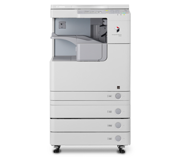
imageRUNNER 2520
imageRUNNER 2520
The compact device that is built for productivity
Running at 20ppm, the imageRUNNER 2520 offers a
compact suite of workgroup functionalities. From network printing to
built-in duplex, this multi-functional device is your choice for
reliable, professional documents.
- Multi-function network device: copy, print, colour scan
- Output speed: 20ppm (mono)
- Standard duplex printing and support for USB print and scan
|
| Images are for illustration purpose only |
Print, copy and scan
With the standard copy and network printing
feature on the device, the imageRUNNER 2520 is able to output at 20
pages per minute in A4 size. Using Canon Network ScanGear software, you
can import scanned colored documents to your PC to archival. Add the
optional 50-sheet feeder to handle multiple-page originals and keep your
business moving.
Standard network printing
This business multi-function device can be
seamlessly connected to your office network for simplified shared
printing among different users. Using the Remote User Interface,
functions such as machine status check, job operations and print
instructions can all be monitored and controlled remotely through the
network directly from your desktop.
Cost-saving duplex output
This imageRUNNER cuts your paper consumption
by half with a standard duplex printing mode, which allows easy printing
or copying on both sides of the paper, without compromise in quality.
Your business may reduce paper by up to 50% – saving resources and the
environment at the same time.
Specifications for imageRUNNER 2520
| Device | imageRUNNER 2520 | |
| Type | Desktop (Reader Combined + Inner Output) | |
| Imaging System | Laser Dry Electrostatic Transfer System | |
| Memory | Standard: | 256MB |
| Maximum: | 512MB | |
| Network Interface | Ethernet (100Base-TX / 10Base-T), USB 2.0 | |
| Warm Up Time | 30 seconds maximum after powering ON
1 second maximum from the Sleep mode |
|
| First Copy Output Time | 6.4 seconds or less | |
| Multiple Copies | 1 to 999 sheets | |
| Magnification | 25% to 400% (1% increment) | |
| Maximum Original Size | Max. A3 / 11" x 17" | |
| Duplex | Standard | |
| Copy / Print Speed | 20ppm | |
| Resolution | Reading: | 600 x 600dpi |
| Writing: | 1200 x 1200dpi | |
| Paper Sources (80gsm) | Paper Cassette: | Standard: 250 sheets paper capacity Maximum: 250 + 3 x 550 sheets paper capacity |
| Stack Bypass: | Standard: 100 sheets paper capacity | |
| Acceptable Paper Weights | Paper Cassette: | 64 to 90gsm |
| Stack Bypass: | 64 to 128gsm | |
| Main Unit Dimensions
(W x D x H) |
565 x 680 x 681mm (with the platen cover) 565 x 693 x 771mm (with the feeder) |
|
| Weight | Approx. 50.5kg | |
| Power Source | 220 - 240V AC, 50 / 60Hz | |
| Maximum Power Consumption | Approx. 1.542KW | |
| Toner Yield (6% Coverage) | Approx. 14,600 sheets (A4) | |
| Drum Yield | Approx. 132,000 sheets (A4) | |
| Print Specification | ||
| PDL | Standard: | UFR II LT |
| Optional: | PCL 5e/6, PS3 | |
| Network OS | Windows 2000 / XP / Server2003 / Vista / Server2008 / Win7, Mac OSX (10.4.9 or later) | |
| Network ScanGear Specification | ||
| Supported OS | Windows 2000 / XP / Server2003 / Vista / Server2008 / Win7 | |
| Resolution | BW: | Up to 600 x 600dpi |
| CL: | Up to 300 x 300dpi | |
Consumables for imageRUNNER 2520
Paper
- Colour/Tinted Paper
Tinted paper for enhancing your office documents. Guaranteed for high speed copying and printing. Ensures smooth and easy machine runnability. Wide range of shades available. Produced with 100% chlorine-free bleached pulp with the environment at heart.
For further enquiries and information please click here.
Size Quantity Price A4 (80gsm)
Available in Ivory, Lagoon (Green), Lavender, Ocean (Blue), Pink, Rose & Yellow500 sheets/ream (5/ctn) csp.marketing@canon.co.in - Canon Business High Grade
High grade white paper for general office use. Good opacity eliminates show-through with double sided copying and printing.
For further enquiries and information please click here.
Size Quantity Price A4 (70gsm) 500 sheets/ream (5/ctn) csp.marketing@canon.co.in A4 (80gsm) 500 sheets/ream (5/ctn) csp.marketing@canon.co.in A3 (70gsm) 500 sheets/ream (5/ctn) csp.marketing@canon.co.in A3 (80gsm) 500 sheets/ream (5/ctn) csp.marketing@canon.co.in 
- Canon Premium
Premium white paper with consistent performance and reliability for high quality volume copying and printing. Produced using 100% Eucalyptus fibre offering high bulk and opacity.
For further enquiries and information please click here.
Size Quantity Price A4 (70gsm) 500 sheets/ream (5/ctn) csp.marketing@canon.co.in A4 (80gsm) 500 sheets/ream (5/ctn) csp.marketing@canon.co.in 
- Canon Océ 100% Recycled Plus
Recycled quality paper produced with 100% post-consumer waste, without optical whiterners. Awarded Blue Angel award of Germany.
For further enquiries and information please click here.
Size Quantity Price A4 (80gsm) 500 sheets/ream (5/ctn) csp.marketing@canon.co.in A3 (80gsm) 500 sheets/ream (5/ctn) csp.marketing@canon.co.in - Canon Océ Top Colour (FSC)
Complete range of superior satinated uncoated quality paper for high impact colour documents and presentations. Smoothness and whiteness of paper enables prints with a distinct and vivid appearance.
For further enquiries and information please click here.
Size Quantity Price A4 (90gsm) 500 sheets/ream (5/ctn) csp.marketing@canon.co.in A4 (100gsm) 500 sheets/ream (5/ctn) csp.marketing@canon.co.in A4 (120gsm) 500 sheets/ream (4/ctn) csp.marketing@canon.co.in A3 (90gsm) 500 sheets/ream (5/ctn) csp.marketing@canon.co.in A3 (100gsm) 500 sheets/ream (4/ctn) csp.marketing@canon.co.in A3 (120gsm) 500 sheets/ream (4/ctn) csp.marketing@canon.co.in 
- Canon Office (FSC)
Premium quality, extra bright white paper with consistent performance and reliability for everyday use. High opacity eliminates show-through with double sided copying and printing. Raw materials obtained from sustainable managed forest are used in making this paper.
For further enquiries and information please click here.
Size Quantity Price A4 (80gsm) 500 sheets/ream (5/ctn) csp.marketing@canon.co.in 
Langganan:
Komentar (Atom)